
Ever since I’m back from Svalbard, I’ve been thinking about building an all sky camera. During dark season, there are a lot of tourists on the island for Northern lights (Aurora Borealis), even though it is actually too far north up there to see them consistently. Sometimes they aren’t seen for weeks due to snow storms or lack of solar activity, and other times they are just not noticed due to the fact that is very cold outside and few people are spending hours outside due to that cold.
There is an all sky camera on the island, but it is not always online and when there are northern lights visible you have to look at the camera feed at the right time to notice them. I could use that feed to provide realtime alerts, but it would be better to have my own camera to use, even more so as the existing feed is from a 15 kilometers out of town at the Kjell Henriksen Observatory.
An out-of-the box all-sky camera will cost at least €2000 and runs into much higher numbers, so that’s not an option for me.
My plan is thus very simple; I’ll build my own budget friendly all-sky camera, set it up on the island and build an app that provides real-time alerts. This post describes the first part, and gives you all the information you’ll need to build your own. It also includes a cost breakdown and the STL/F3D files to print the custom part.
Requirements
There are some requirements to consider from the start;
- The enclosure should be waterproof, as there is a lot of snow during winter and rain during the summer
- The camera should operate at temperatures down to -30°C, and should be able to withstand temperatures down to -50°C.
- There should be as few cables as possible to the camera
- Maintenance should be as easy as possible, and not require full re-assembly.
I decided on using the latest Raspberry Pi at the time, which was version 4 when I started this project. It has a camera input and support for ethernet, which are both also required.
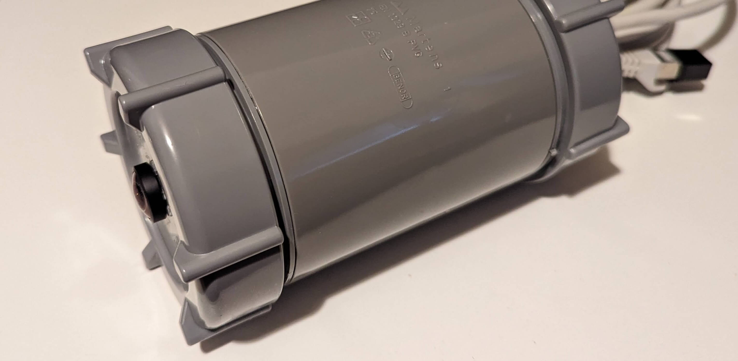
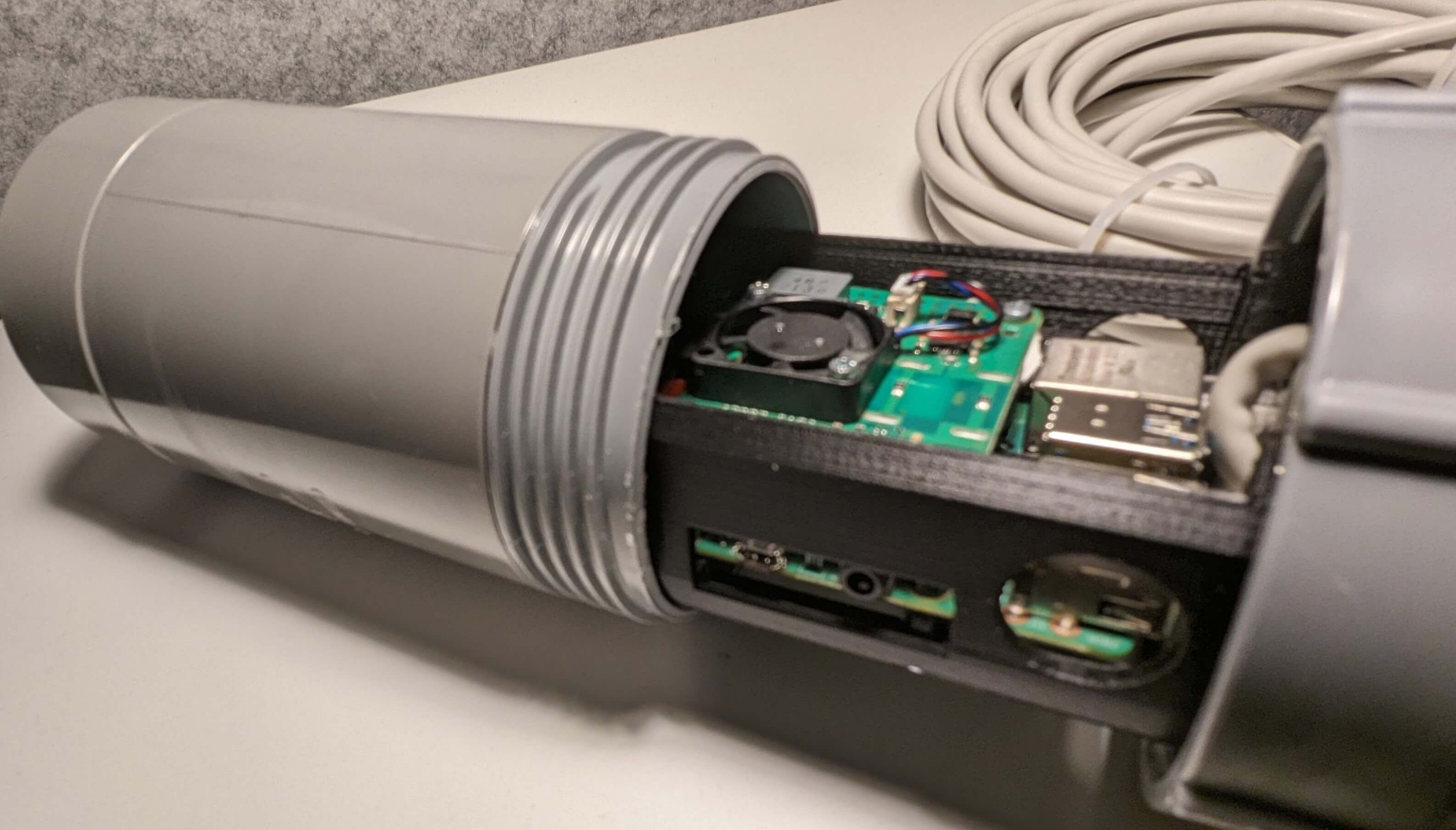
For the waterproof enclosure (1) that can withstand extreme temperatures (2), I did have a box that’s waterproof and has a seal, but I suspect that it is the wrong material and too thin to withhold the extreme temperatures. There are a lot of PVC sewer pipe materials available at my local DIY store, and as those have to deal with a lot of water I decided to use that as my base material. Initially I went for a tube with a diameter of 11cm, but when mock-assembling all the parts I noticed that in the right orientation the 7.5cm diameter tubing would also work.
To reduce the amount of cables running to the camera (3), I decided on Power over Ethernet (PoE), so the ethernet cable for connectivity can also be used to provide power. There is a PoE shield available for the raspberry pi, and although it does produce a lot of heat, that can actually be used to our advantage to keep the dome clear of fog as warm heat rises. We’ll keep air flow inside the case as a consideration when designing the next steps, next to also using silica gel to keep the humidity in the camera to a minimum.
We could use Wi-Fi to connect the camera to the internet and rely on batteries, but capacity is much lower in extreme cold for most battery types, so PoE seems like the more reliable choice here. That also means less maintenance in battery replacements.
Speaking of cold(2): As this camera is going to be high above the arctic circle, the temperatures will be between +5°C and -30°C. As there is a lot of snowfall, the heat of the raspberry should be able to clear off any snow from the dome by melting it. This camera will only be operational during polar night, as half of the year the sun is permanently above the horizon, so we don’t have to worry about cooling the device during those summer months (even though the temperature doesn’t go much above freezing anyway).
Apart from these initial design constraints, I decided on PVC screw lids to allow for easy access to the raspberry pi board for even easier maintenance access (4).
v0: Test fit and mount position
After taking all of this in consideration, It was time to run some test prints. In my initial design I didn’t want to spend hours waiting for my 3D printer, so I decided to test-fit parts and come up with the mount position with as little material as possible.
The camera should be pointing up, and the raspberry pi and PoE hat only fit in one orientation. After checking for space for the camera ribbon everything seems good to go, so time for a serious prototype!
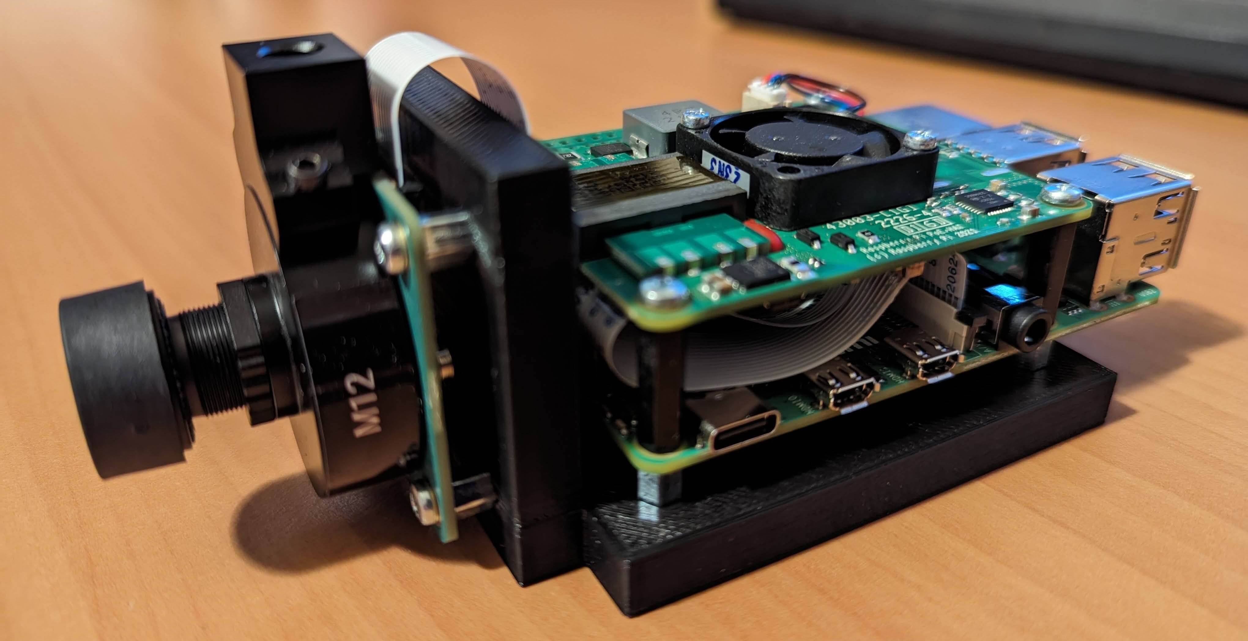
v1: Initial prototype with through-hole camera
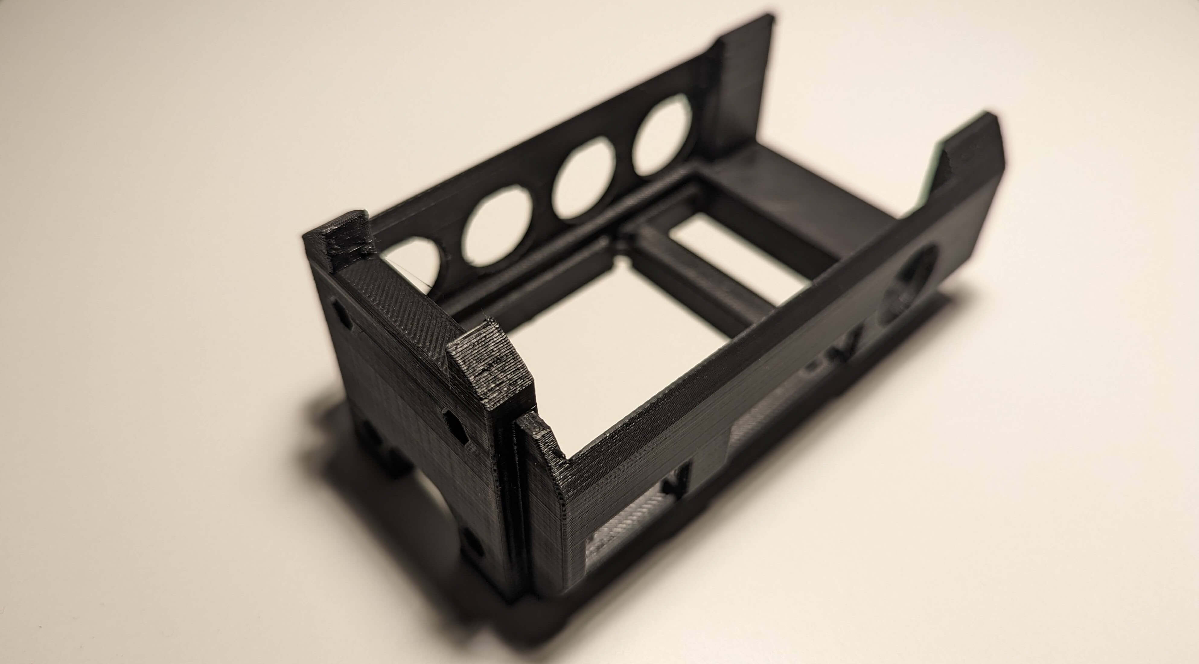
There are hexagonal holes for the screw standoffs, and countersunk holes for the corresponding screws. The shape of the outer perimeter allows for airflow inside the piping, and some holes below and next to the location of the raspberry pi allows for extra airflow. A cutout on the top of the camera mount allows for a ribbon cable to run through.
In this version, contrary to the picture at the top of the article, I was still thinking about a through-hole camera. As both sides of the tube of this version had a screw lid, I had to prevent the camera from freely rotating inside the tube to fix the orientation. To do that, I decided on an extra rotation clamp that could be fit to the top part, prevent the camera from unscrewing:
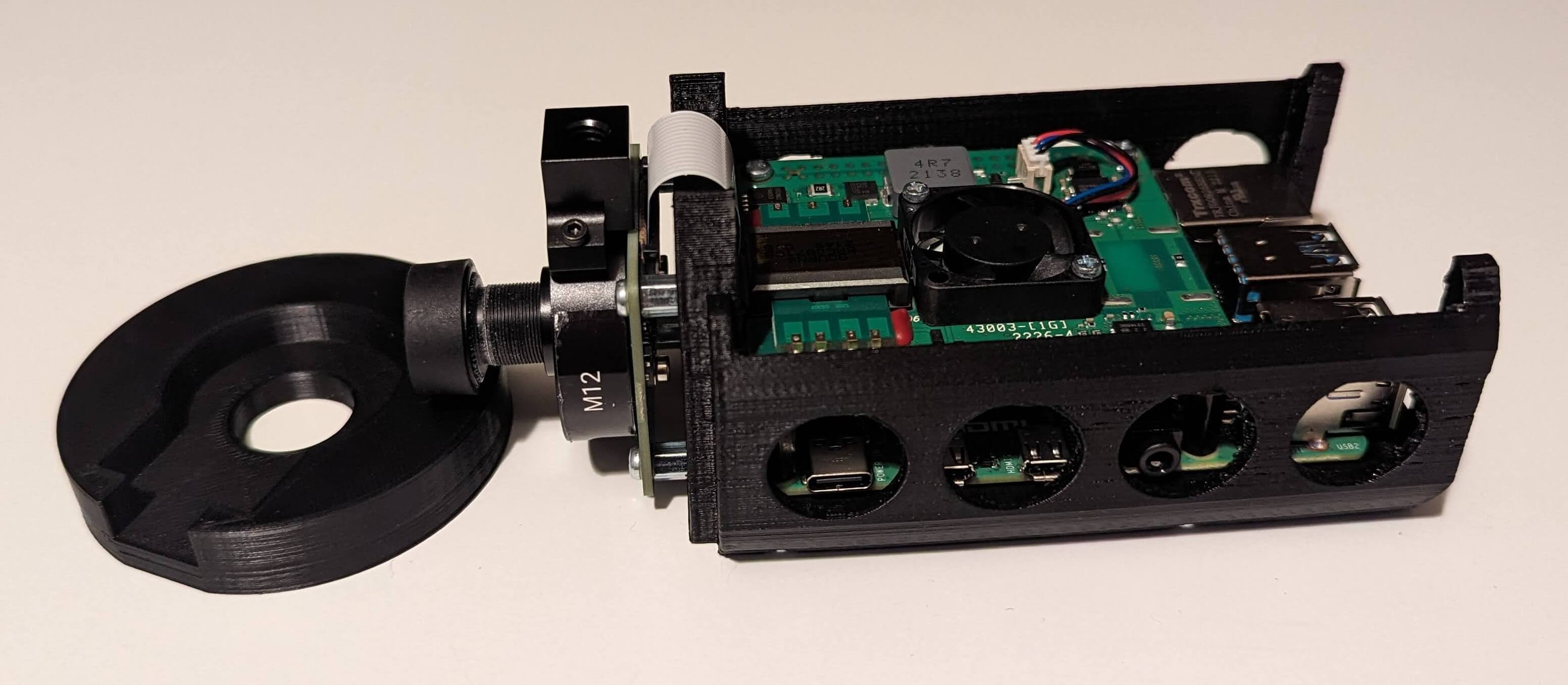
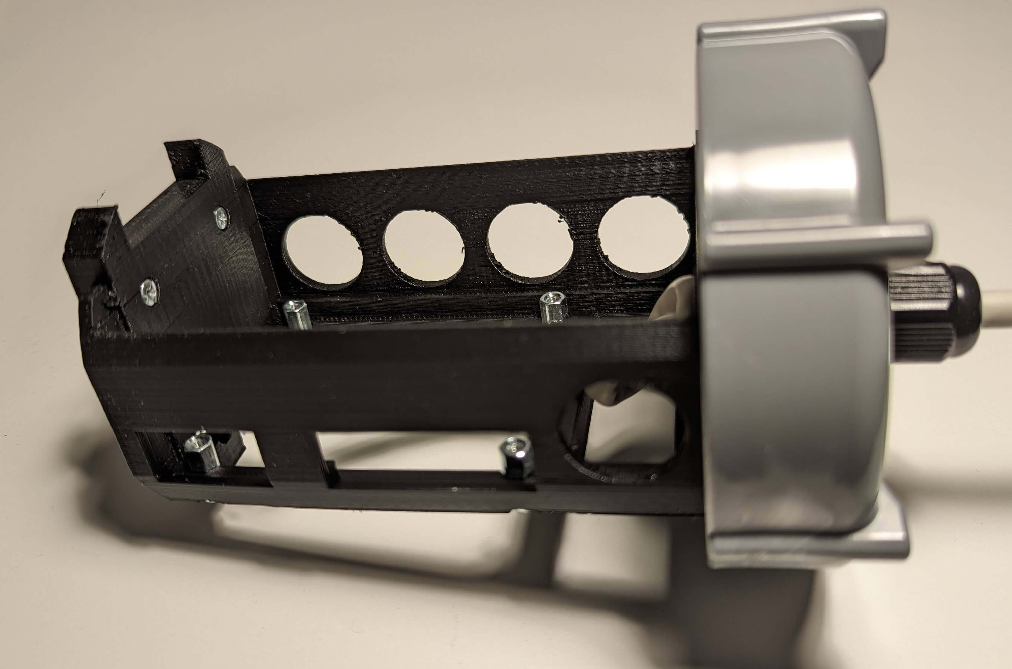
The M12 camera mount fits snugly inside the clamp,
Which is firmly glued to the top screw lid to prevent rotation independent of the top lid.
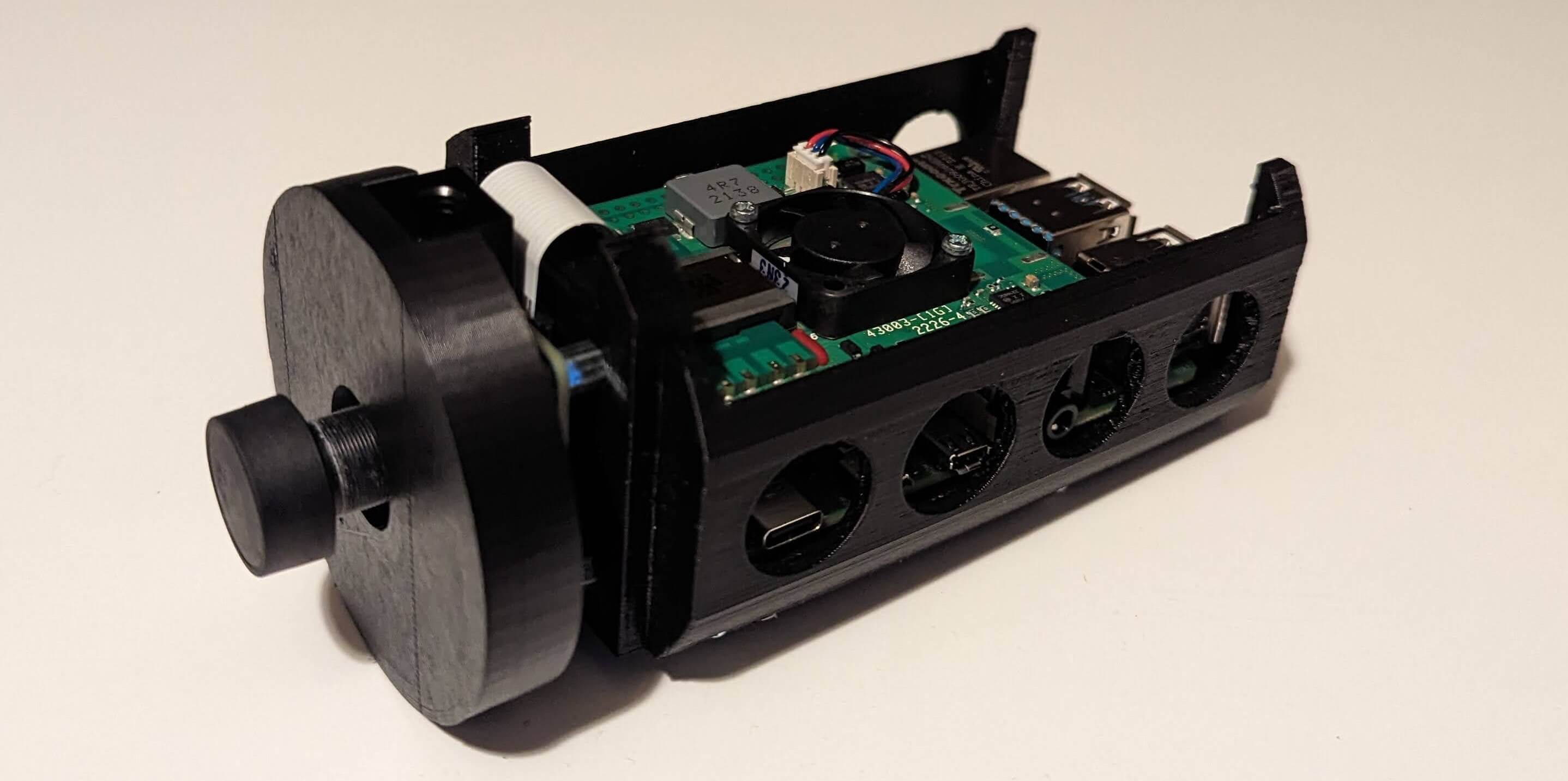
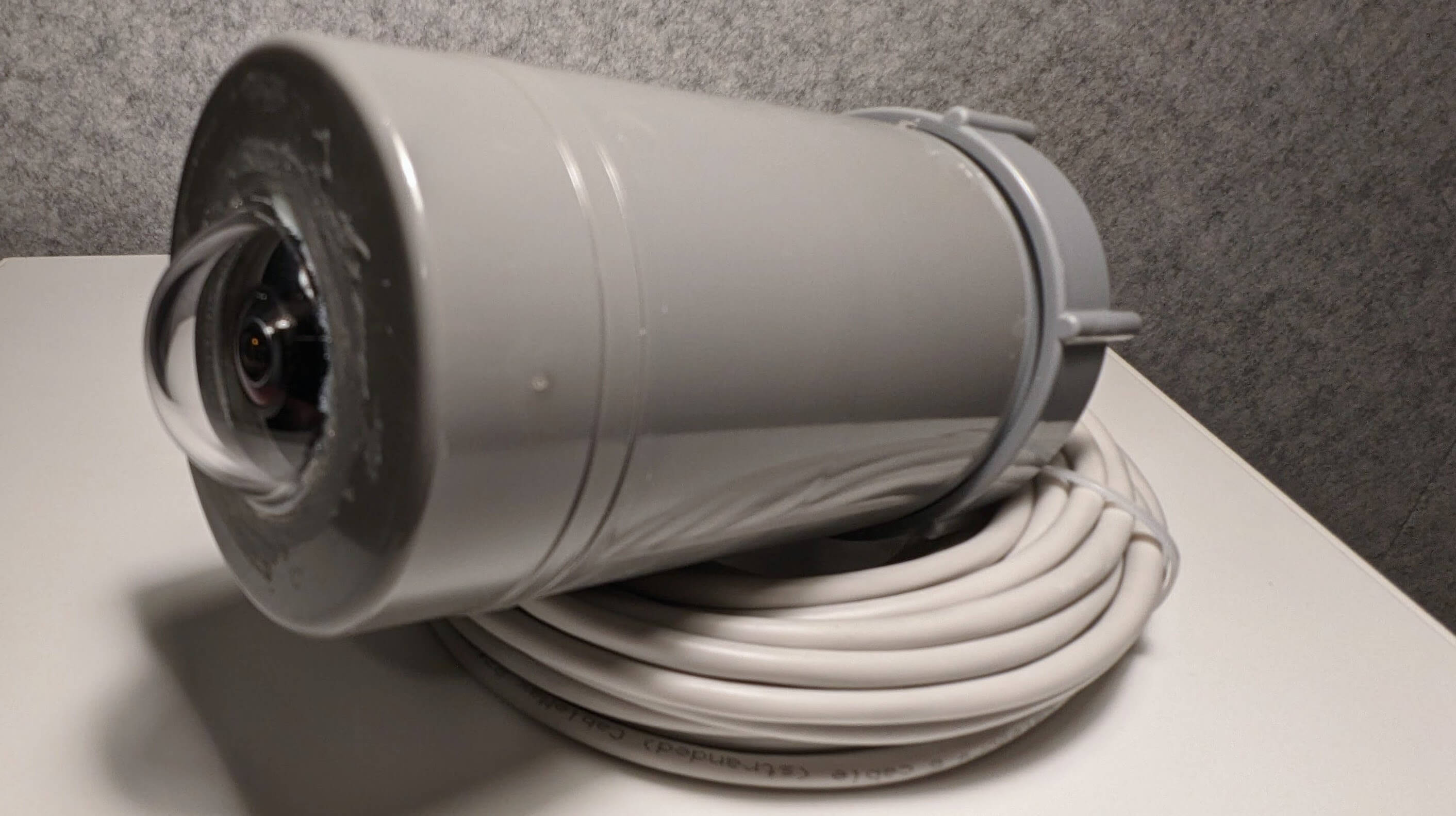
When screwed into place, this is what our camera now looks like:
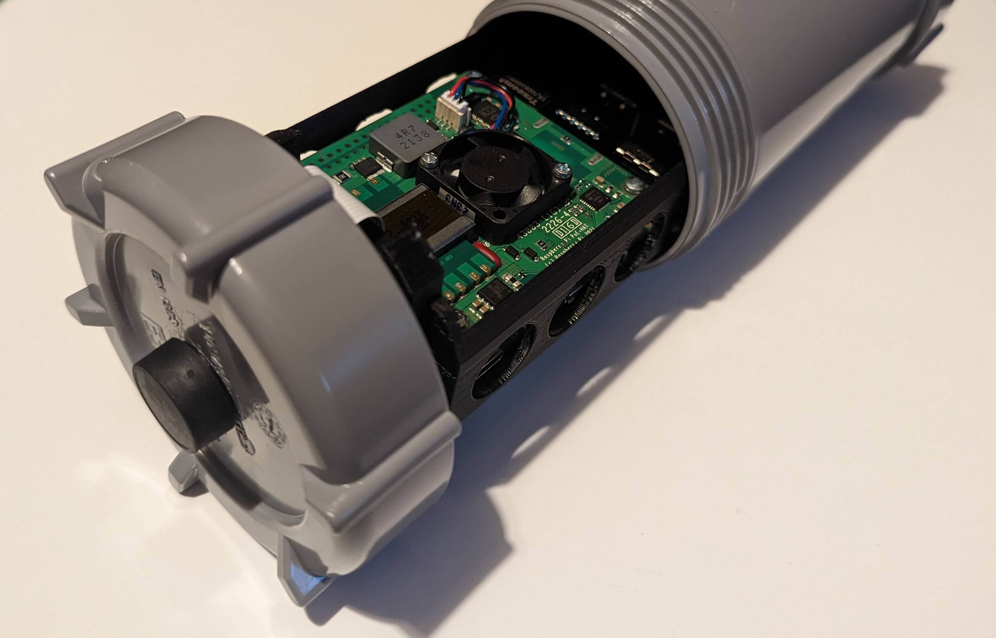
At this point, I had been looking for camera-quality acrylic dome to protect the camera from the harsh climate, and the idea was to put a dome over the entire surface of the lid. When I found a dome - one for a security camera - it was much smaller than I had expected. This proved to be a new problem: The smaller dome together with the indentation in the PVC screw lid would result in melted snow or water building up in the lid.
v2: Improved design
V2 then was indented to solve this issue. As I finally had a dome to work with, I started of with some new PVC parts. Instead of a PVC screw lid this is just an end stop glued to a PVC connector pipe using some connector end caps.
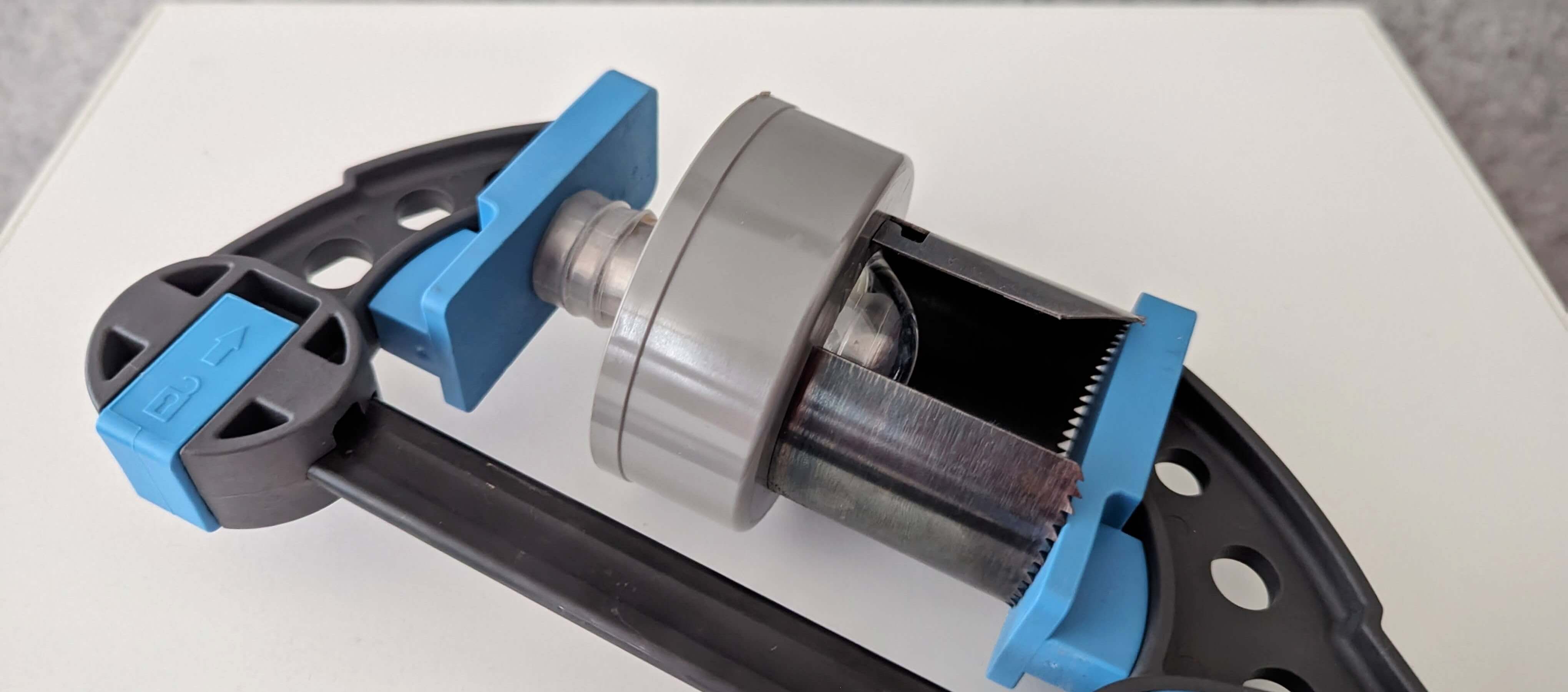
As both parts have weird geometry, keeping the parts together while the glue was curing seemed quite troubling, but I managed to combine some bearings and a hole-saw to clamp the pieces together with a glue clamp.
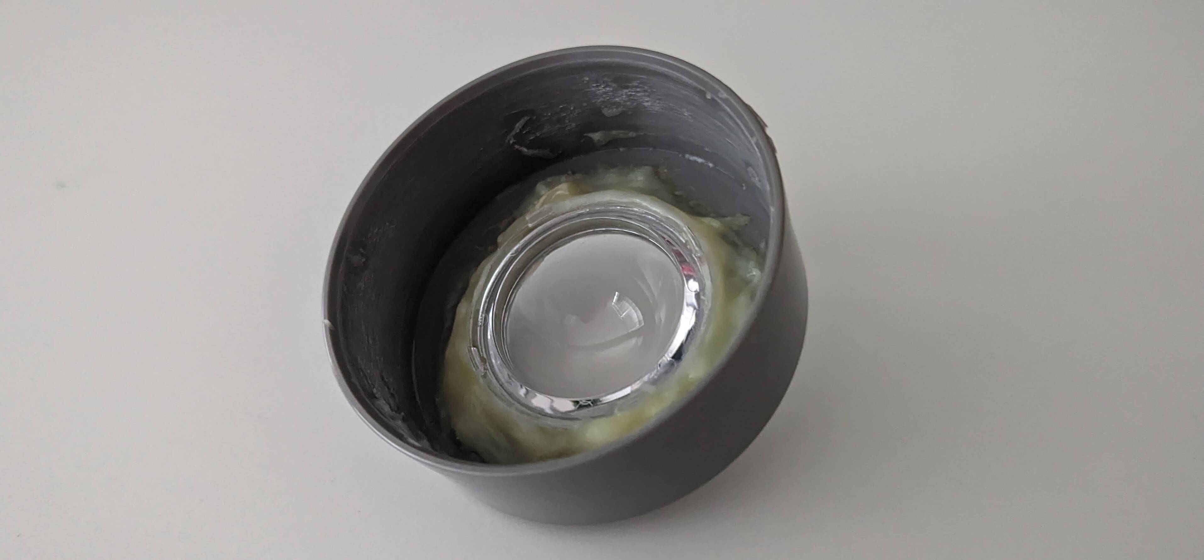
Using the strongest 2-component glue I could find resulted in the lid looking like this from the inside. Looks waterproof to me!
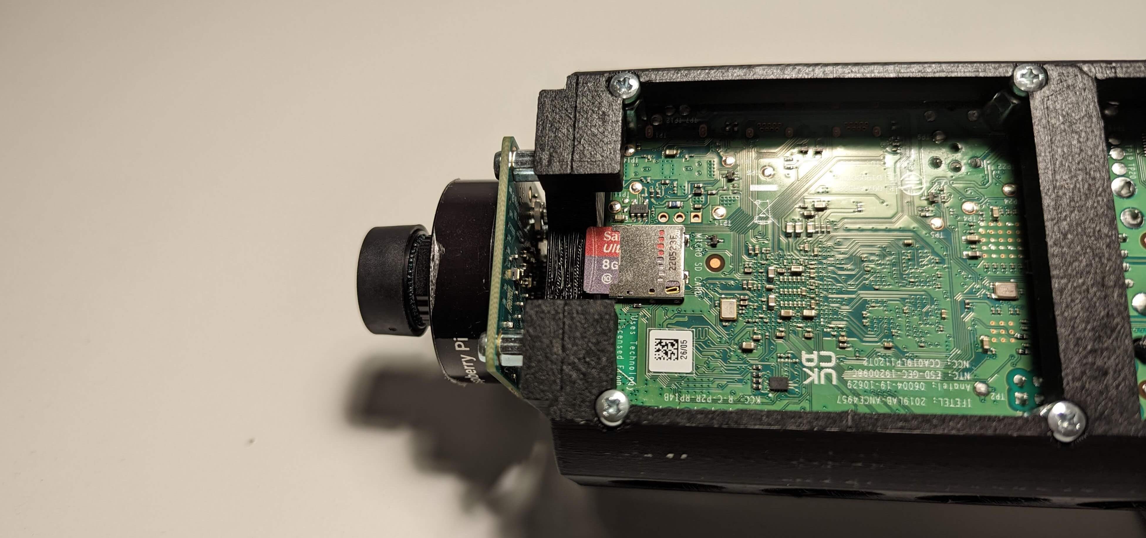
Now it was time to fix some issues in the previous 3D design. First of all, due to the change of parts there was now more room available inside the tube, so I had to extend it a bit. Also, there was no easy way to replace the micro SD card, which resulted in me having to reassemble the entire camera a couple of times, so I had to fix that. The design now looked like this:
After a quick test-fit everything looked in order, so I could continue the assembly.
With this new design, the camera is now not attached to the top anymore and can freely rotate independently of it. The previous design posed an issue when screwing and unscrewing the top or bottom lid: The waterproof cable gland would prevent the cable from rotating when secured, but that would mean that when either of the lids would be (un)screwed the cable would tangle up. As the camera is not relying on the top mount anymore, we can now attach it to the bottom, solving this issue as well!
The ethernet cable gets a knot for strain-relief, and then the 3D-printed mount can get glued to the bottom lid. Then we can assemble the hex standoffs, and screw in the screws from the bottom and the inside.
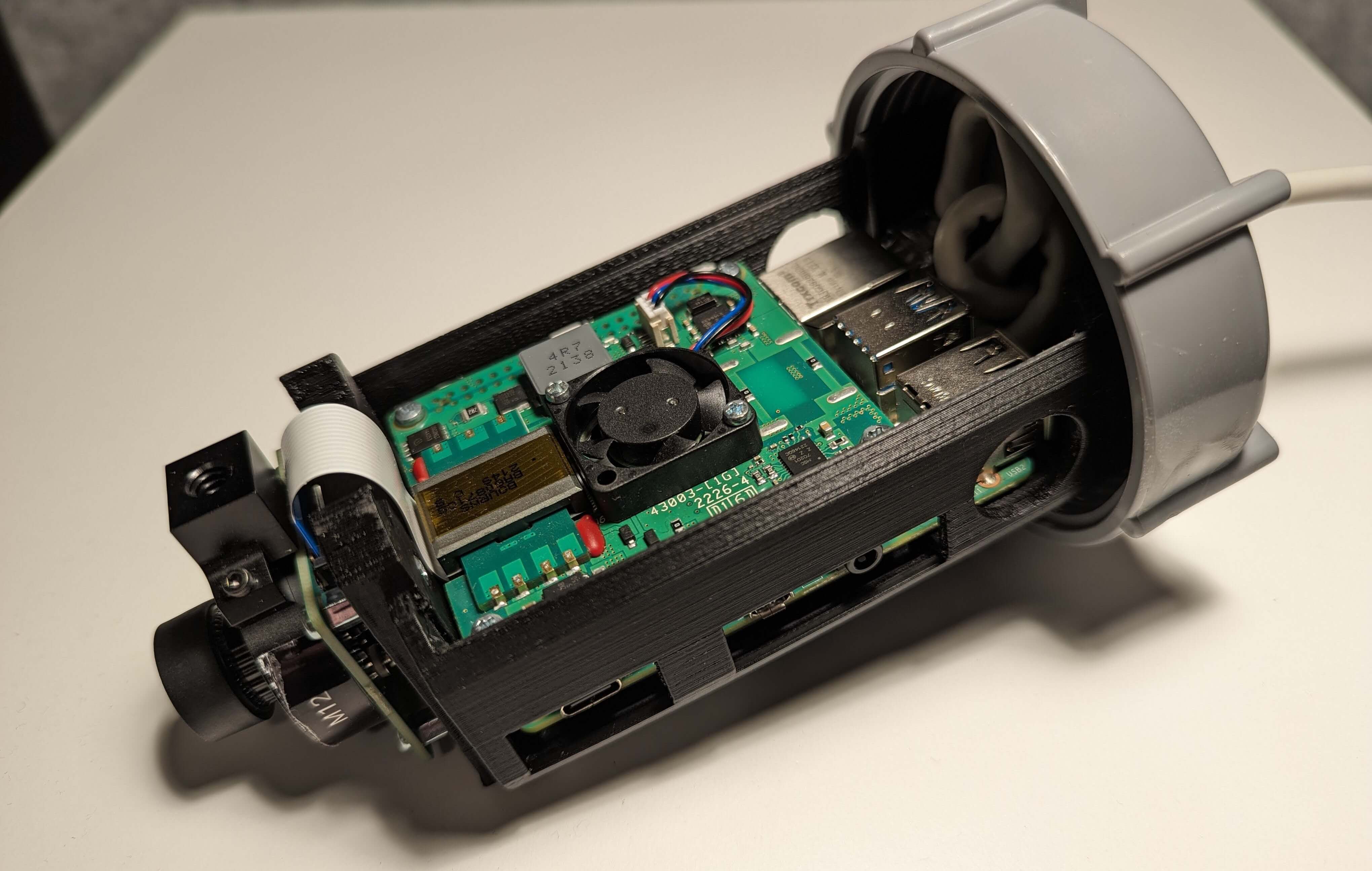
Next up, we can install the Raspberry Pi itself. After inserting the ethernet cable and putting that away neatly, the board fits on the hex standoffs. The next set of standoffs can be used to mount the board to the case. The camera can be mounted on the top again, and the cable ribbon can be attached to the board. The stacking headers are mounted now as well to make sure that the PoE board fits without breaking the camera ribbon.

Next up, we can add the PoE hat. We have to make sure that the camera ribbon is tucked away nicely between the two boards, while still allowing for airflow from the fan to reach the CPU. Also, the turn around the mount should not be too big, as the cutout allows for the cable to pass around it, but a loop to big here would result in the PVC tube denting that ribbon.
Next, it’s time to add an SD card with headless Raspbian installed. A cutout is left here after the previous version required complete reassembly when anything was wrong with the OS.
Finally, we can put everything together and screw the lid with the assembled mount on the case with the Acrylic dome. We have a fully completed camera!
I won’t go into much detail on the OS installation as there are enough guides available on that already, but I decided on a headless Raspbian installation an the Allsky software available on Github to finish off this build.
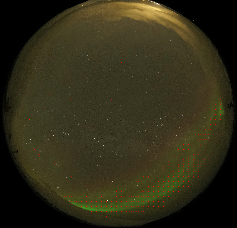
In the next part, I’ll go into how to detect northern lights from an image like this:
Parts & Costs
If you want to reproduce this build, below is the parts list including the amount of money I spent on this. You can find the 3d-files on Thingiverse or this GitHub Repository
| Name | Cost | Qty. | Total |
|---|---|---|---|
| Raspberry Pi 4 Model B - 4 GB | € 47.95 | 1 | € 47.95 |
| Raspberry Pi 4 PoE+ HAT (2021) | € 24.95 | 1 | € 24.95 |
| HDMI - Micro HDMI cable 1.5m | € 7.95 | 1 | € 7.95 |
| Raspberry Pi - HQ Camera M12 mount | € 60.95 | 1 | € 60.95 |
| M12 High Resolution Lens, 14ML, 184.6° Ultra wide angle lens | € 14.95 | 1 | € 14.95 |
| Brass M2.5 Standoffs 16mm - black plated - 2 pack | € 1.50 | 2 | € 3.00 |
| 4 pin GPIO Header - 2x2 Female | € 2.50 | 1 | € 2.50 |
| 40-pin GPIO Stacking Header - 2x20 Female | € 1.95 | 1 | € 1.95 |
| AXIS TM3813 Dome Clear | € 53.24 | 1 | € 53.24 |
| PVC Glue connector 75mm | € 2.49 | 1 | € 2.49 |
| PVC end cap with screw lid 75mm | € 3.49 | 1 | € 3.49 |
| PVC end cap 75mm | € 1.99 | 1 | € 1.99 |
| PVC closing cap 75mm | € 1.30 | 2 | € 2.60 |
| PVC glue | € 7.19 | 1 | € 7.19 |
| Ubiquiti Power over Ethernet injector 48Volt | € 24.00 | 1 | € 24.00 |
| Waterproof Cable gland 3.0 - 6.5mm, Nylon | € 0.54 | 1 | € 0.54 |
| Bison Combi plastic glue | € 11.99 | 1 | € 11.99 |
| PLA 3D printer filament (Price per kg) | € 25.99 | 53g | € 1.38 |
| Total | € 273.11 |